|
Electronic Components Datasheet Search |
|
|
Electronic Components Datasheet Search |
|
IP1202PBF Datasheet(PDF) 28 Page - International Rectifier |
|
|
|||||||||||||||||||||||||||||
IP1202PBF Datasheet(HTML) 28 Page - International Rectifier |
|
|
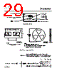
28 / 29 page  www.irf.com 28 iP1202PbF Fig.33: Mechanical Drawing Refer to the following application notes for detailed guidelines and suggestions when implementing iPOWIR Technology products: AN-1028: Recommended Design, Integration and Rework Guidelines for International Rectifiers iPOWIR Technology BGA Packages This paper discusses the assembly considerations that need to be taken when mounting iPOWIR BGAs on printed circuit boards. This includes soldering, pick and place, reflow, inspection, cleaning and reworking recommendations. AN-1029: Optimizing a PCB Layout for an iPOWIR Technology Design This paper describes how to optimize the PCB layout design for both thermal and electrical performance. This includes placement, routing, and via interconnect suggestions. AN-1030: Applying iPOWIR Products in Your Thermal Environment This paper explains how to use the Power Loss and SOA curves in the data sheet to validate if the operating conditions and thermal environment are within the Safe Operating Area of the iPOWIR product. AN-1043: Stabilize the Buck Converter with Transconductance Amplifier. AN-1047: Graphical solution to two branch heatsinking Safe Operating Area This paper is a suppliment to AN-1030 and explains how to use the double side Power Loss and SOA curves in the data sheet to validate if the operating conditions and thermal environment are within the Safe Operating Area of the iPOWIR product. AN-1053: Power Sequencing Techniques using iP1201 and iP1202PbF. 0.12 [.005] C 2. DIMENS IONS ARE S HOWN IN MILLIMETERS [INCHES]. 3. CONTROLLING DIMENSION: MILLIMETER 1. DIMENS IONING & TOLERANCING PER ASME Y14.5M-1994. NOTES: (2X 0.625 [.025]) 2.33 [.0917] 2.11 [.0831] TOP VIEW BOTTOM VIEW SIDE VIEW 2.78 [.1094] 2.46 [.0968] C 0.45 [.0177] 0.35 [.0138] PACKAGE BODY. BALL DIAMETER, IN A PLANE PARALLEL TO DATUM C. SPHERICAL CROWNS OF THE SOLDER BALLS. 4. SOLDER BALL POS ITION DESIGNATION PER JESD 95-1, SPP-010. 7 SOLDER BALL DIAMETER IS MEAS URED AT THE MAXIMUM SOLDER 5 PRIMARY DATUM C (SEATING PLANE) IS DEFINED BY THE 6 BILATERAL TOLERANCE ZONE IS APPLIED TO EACH SIDE OF THE 5 0.15 [.006] C CORNER ID BALL A1 2X 6 15.50 [.610] B 9.25 [.364] A 0.15 [.006] C 2X 6 0.15 [.006] CA B 0.08 [.003] C 161X Ø 0.45 [.0178] 0.55 [.0216] 7 0.40 [.016] 2X 0.80 [.032] 27X 8. NOT TO SCALE |
|
Link URL |
| Does ALLDATASHEET help your business so far? [ DONATE ] |
About Alldatasheet | Advertisement | Contact us | Privacy Policy | Link to Datasheet | Link Exchange | Manufacturer List All Rights Reserved©Alldatasheet.com |
| Russian : Alldatasheetru.com | Korean : Alldatasheet.co.kr | Spanish : Alldatasheet.es | French : Alldatasheet.fr | Italian : Alldatasheetit.com Portuguese : Alldatasheetpt.com | Polish : Alldatasheet.pl | Vietnamese : Alldatasheet.vn Indian : Alldatasheet.in | Mexican : Alldatasheet.com.mx | British : Alldatasheet.co.uk | New Zealand : Alldatasheet.co.nz |
|
Family Site : ic2ic.com |
icmetro.com |
 English ▼
 English
 Chinese
 German
 Japanese
 Russian
 Korean
 Spanish
 French
 Italian
 Portuguese
 Polish
 Vietnamese
 Indian
 Mexican
 British
 New Zealand