|
Electronic Components Datasheet Search |
|
|
Electronic Components Datasheet Search |
|
DS1306EN/TR Datasheet(PDF) 12 Page - Dallas Semiconductor |
|
|
|||||||||||||||||||||||||||||
DS1306EN/TR Datasheet(HTML) 12 Page - Dallas Semiconductor |
|
|
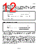
12 / 21 page  DS1306 12 of 21 ADDRESS AND DATA BYTES Address and data bytes are shifted MSB first into the serial data input (SDI) and out of the serial data output (SDO). Any transfer requires the address of the byte to specify a write or read to either a RTC or RAM location, followed by one or more bytes of data. Data is transferred out of the SDO for a read operation and into the SDI for a write operation (Figures 6 and 7). Figure 6. SPI SINGLE-BYTE WRITE Figure 7. SPI SINGLE-BYTE READ The address byte is always the first byte entered after CE is driven high. The most significant bit (A7) of this byte determines if a read or write takes place. If A7 is 0, one or more read cycles occur. If A7 is 1, one or more write cycles occur. Data transfers can occur one byte at a time or in multiple-byte burst mode. After CE is driven high an address is written to the DS1306. After the address, 1 or more data bytes can be written or read. For a single-byte transfer, one byte is read or written and then CE is driven low. For a multiple-byte transfer, however, multiple bytes can be read or written to the DS1306 after the address has been written. Each read or write cycle causes the RTC register or RAM address to automatically increment. Incrementing continues until the device is disabled. When the RTC is selected, the address wraps to 00h after incrementing to 1Fh (during a read) and wraps to 80h after incrementing to 9Fh (during a write). When the RAM is selected, the address wraps to 20h after incrementing to 7Fh (during a read) and wraps to A0h after incrementing to FFh (during a write). * SCLK CAN BE EITHER POLARITY. * SCLK CAN BE EITHER POLARITY. |
|
|
Link URL |
| Does ALLDATASHEET help your business so far? [ DONATE ] |
About Alldatasheet | Advertisement | Contact us | Privacy Policy | Link to Datasheet | Link Exchange | Manufacturer List All Rights Reserved©Alldatasheet.com |
| Russian : Alldatasheetru.com | Korean : Alldatasheet.co.kr | Spanish : Alldatasheet.es | French : Alldatasheet.fr | Italian : Alldatasheetit.com Portuguese : Alldatasheetpt.com | Polish : Alldatasheet.pl | Vietnamese : Alldatasheet.vn Indian : Alldatasheet.in | Mexican : Alldatasheet.com.mx | British : Alldatasheet.co.uk | New Zealand : Alldatasheet.co.nz |
|
Family Site : ic2ic.com |
icmetro.com |
 English ▼
 English
 Chinese
 German
 Japanese
 Russian
 Korean
 Spanish
 French
 Italian
 Portuguese
 Polish
 Vietnamese
 Indian
 Mexican
 British
 New Zealand