|
Electronic Components Datasheet Search |
|
|
Electronic Components Datasheet Search |
|
AD9142ABCPZ Datasheet(PDF) 29 Page - Analog Devices |
|
|
|||||||||||||||||||||||||||||
AD9142ABCPZ Datasheet(HTML) 29 Page - Analog Devices |
|
|
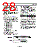
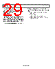
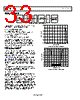
29 / 73 page  AD9142A Data Sheet Interface Timing Requirements The following example shows how to calculate the optimal delay at the data source to achieve the best sampling timing in the delay line interface mode: • fDCI = 200 MHz • Delay setting = 0 The shadow area in Figure 38 is the interface setup and hold time window set to 0. To optimize the interface timing, this window must be placed in the middle of the data transitions. Because the input is double data rate, the available data period is 2.5 ns. Therefore, the optimal data bus delay, with respect to the DCI at the data source, can be calculated as ns 13 . 0 25 . 1 38 . 1 2 2 |) | | (| = − = − + = PERIOD DATA H S DELAY t t t t SPI Sequence to Enable Delay Line Interface Mode Use the following SPI sequence to enable the delay line interface mode: 1. 0x5E → 0x00 /* Configure the delay setting */ 2. 0x5F → 0x60 3. 0x0D → 0x16 /* DC couple DCI */ 4. 0x0A → 0x00 /* Turn off DLL and duty cycle correction */ Rev. A | Page 28 of 72 |
|
Link URL |
| Does ALLDATASHEET help your business so far? [ DONATE ] |
About Alldatasheet | Advertisement | Contact us | Privacy Policy | Link to Datasheet | Link Exchange | Manufacturer List All Rights Reserved©Alldatasheet.com |
| Russian : Alldatasheetru.com | Korean : Alldatasheet.co.kr | Spanish : Alldatasheet.es | French : Alldatasheet.fr | Italian : Alldatasheetit.com Portuguese : Alldatasheetpt.com | Polish : Alldatasheet.pl | Vietnamese : Alldatasheet.vn Indian : Alldatasheet.in | Mexican : Alldatasheet.com.mx | British : Alldatasheet.co.uk | New Zealand : Alldatasheet.co.nz |
|
Family Site : ic2ic.com |
icmetro.com |
 English ▼
 English
 Chinese
 German
 Japanese
 Russian
 Korean
 Spanish
 French
 Italian
 Portuguese
 Polish
 Vietnamese
 Indian
 Mexican
 British
 New Zealand