|
Electronic Components Datasheet Search |
|
|
Electronic Components Datasheet Search |
|
STPMS2 Datasheet(PDF) 23 Page - STMicroelectronics |
|
|
|||||||||||||||||||||||||||||
STPMS2 Datasheet(HTML) 23 Page - STMicroelectronics |
|
|
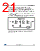
23 / 36 page  STPMS2 Theory of operation DocID16525 Rev 5 23/36 Figure 19: Block diagram and definition of DFE digital signals 9.3.1 Decoder for different modes of operations The decoder defines the operating mode according to the state of the bootstrap MS0, MS1, MS2 and MS3 pins. Two different operational modes can be defined: Hard mode: in this case the device configuration is bootstrapped at startup and signals come from VIN and VIP for voltage channels, and CIP and CIN for current channels or from internal BIST DAC. Soft mode: in this mode all possible settings from hard mode are accessible, as well as additional settings such as dither and chopper signal frequencies and operation. 9.3.2 Generator for clock frequency Chopper and BIST frequency generator The chopper block generates the chopper frequencies and BIST signals for the voltage and current channels. The BIST DAC output levels are appropriately adjusted for the current channel according to the gain selection, while for the voltage channel the max. DC voltage is used. The levels are 300 mV for the voltage channel and 300 mV / 150 mV / 75 mV / 37.5 mV for the current channel, in accordance with gain settings 2/4/8/16, respectively in soft mode, while 300 mV / 37.5 mV based on gain settings 2/16 in hard mode. Pseudo random The pseudo random block generates pseudo random signals for the voltage and current channels. These random signals are used to implement a dithering technique to decorrelate the output of the modulators and avoid accumulation points on the frequency spectrum. |
|
Link URL |
| Does ALLDATASHEET help your business so far? [ DONATE ] |
About Alldatasheet | Advertisement | Contact us | Privacy Policy | Link to Datasheet | Link Exchange | Manufacturer List All Rights Reserved©Alldatasheet.com |
| Russian : Alldatasheetru.com | Korean : Alldatasheet.co.kr | Spanish : Alldatasheet.es | French : Alldatasheet.fr | Italian : Alldatasheetit.com Portuguese : Alldatasheetpt.com | Polish : Alldatasheet.pl | Vietnamese : Alldatasheet.vn Indian : Alldatasheet.in | Mexican : Alldatasheet.com.mx | British : Alldatasheet.co.uk | New Zealand : Alldatasheet.co.nz |
|
Family Site : ic2ic.com |
icmetro.com |
 English ▼
 English
 Chinese
 German
 Japanese
 Russian
 Korean
 Spanish
 French
 Italian
 Portuguese
 Polish
 Vietnamese
 Indian
 Mexican
 British
 New Zealand