|
Electronic Components Datasheet Search |
|
|
Electronic Components Datasheet Search |
|
MSW2001-200-R Datasheet(PDF) 3 Page - M/A-COM Technology Solutions, Inc. |
|
|
|||||||||||||||||||||||||||||
MSW2001-200-R Datasheet(HTML) 3 Page - M/A-COM Technology Solutions, Inc. |
|
|
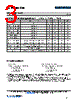
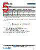
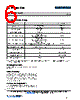
3 / 15 page  SP2T PIN Diode Switch Rev. V1 MSW200x-200 3 3 M/A-COM Technology Solutions Inc. (MACOM) and its affiliates reserve the right to make changes to the product(s) or information contained herein without notice. Visit www.macom.com for additional data sheets and product information. For further information and support please visit: https://www.macom.com/support DS-xxxxxxx 3 MSW2002-200 Electrical Specifications: TA = +25°C, PIN = 0 dBm, Z0 = 50 Ω Parameter Test Conditions Units Min. Typ. Max. Frequency — GHz 2 — 6 TX-Ant Insertion Loss Condition 1 dB — 0.6 0.7 Ant-RX Insertion Loss Condition 2 dB — 0.9 1.0 TX-Ant Return Loss Condition 1 dB 13 15 — Ant-RX Return Loss Condition 2 dB 11 13 — TX-RX Isolation Condition 1 dB 32 34 — RX-TX Isolation Condition 2 dB 11 13 — TX CW Incident Power1 Condition 1, 1.5:1 Source & Load VSWR dBm — — 50 RX CW Incident Power1 Condition 2, 1.5:1 Source & Load VSWR dBm — — 43 TX Peak Incident Power1 Condition 1, 10 µs Pulse Width, 1% Duty Cycle, 1.5:1 Source & Load VSWR (IL) dBm — — 57 Switching Time2 10% - 90% RF Voltage µs — 1.0 1.5 Input IP3 F1 = 500 MHz, F2 = 510 MHz, P1=P2=40 dBm dBm 60 65 — 1. PIN diode DC reverse voltage to maintain high resistance in the OFF PIN diode is determined by RF frequency, incident power, and VSWR as well as by the characteristics of the diode. The minimum reverse bias voltage values are provided in this datasheet. The input signal level applied for small signal testing is approximately 0 dBm. 2. Switching time (50% TTL - 10/90% RF Voltage) is a function of the PIN diode driver performance as well as the characteristics of the diode. An RC “current spiking network” is used on the driver output to provide a transient current to rapidly remove stored charge from the PIN diode. Typical component values are: R = 50 to 220 Ω and C = 470 to 1,000 pF. MACOMs MPD2T28125-700 is the recommended PIN diode driver to interface with the MSW2000-200, MSW2001-200 SP2T and MSW2002-200 switches. Its data sheet is available. Bias State Conditions: Transmit State (TX - ANT in low insertion loss state): a. B1: -100 mA b. B2: +100 mA c. B3: -25 mA, +28 V d. B4: +25 mA Small Signal Receive State (ANT - RX in low insertion loss state): a. B1: +28 V b. B2: +100 mA c. B3: -100 mA, 0 V d. B4: +28 V |
|
|
Link URL |
| Does ALLDATASHEET help your business so far? [ DONATE ] |
About Alldatasheet | Advertisement | Contact us | Privacy Policy | Link to Datasheet | Link Exchange | Manufacturer List All Rights Reserved©Alldatasheet.com |
| Russian : Alldatasheetru.com | Korean : Alldatasheet.co.kr | Spanish : Alldatasheet.es | French : Alldatasheet.fr | Italian : Alldatasheetit.com Portuguese : Alldatasheetpt.com | Polish : Alldatasheet.pl | Vietnamese : Alldatasheet.vn Indian : Alldatasheet.in | Mexican : Alldatasheet.com.mx | British : Alldatasheet.co.uk | New Zealand : Alldatasheet.co.nz |
|
Family Site : ic2ic.com |
icmetro.com |
 English ▼
 English
 Chinese
 German
 Japanese
 Russian
 Korean
 Spanish
 French
 Italian
 Portuguese
 Polish
 Vietnamese
 Indian
 Mexican
 British
 New Zealand