|
Electronic Components Datasheet Search |
|
|
Electronic Components Datasheet Search |
|
ISL8117DEMO2Z Datasheet(PDF) 20 Page - Renesas Technology Corp |
|
|
|||||||||||||||||||||||||||||
ISL8117DEMO2Z Datasheet(HTML) 20 Page - Renesas Technology Corp |
|
|
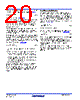
20 / 24 page  ISL8117 FN8666 Rev 4.00 Page 20 of 24 Apr 19, 2018 The output voltage ripple is due to the inductor ripple current and the ESR of the output capacitors as defined by Equation 16: where IL is calculated in Equation 14. High frequency decoupling capacitors should be placed as close to the power pins of the load as physically possible. Be careful not to add inductance in the circuit board wiring that could cancel the usefulness of these low inductance components. Consult with the manufacturer of the load circuitry for specific decoupling requirements. Use only specialized low-ESR capacitors intended for switching regulator applications for the bulk capacitors. In most cases, multiple small case electrolytic capacitors perform better than a single large case capacitor. The stability requirement on the selection of the output capacitor is that the ‘ESR zero’ (fZ) is between 2kHz and 60kHz. This range is set by an internal, single compensation zero at 8.8kHz. The ESR zero can be a factor of five on either side of the internal zero and still contribute to increased phase margin of the control loop. This requirement is shown in Equation 17: In conclusion, the output capacitors must meet the following criteria: 1. They must have sufficient bulk capacitance to sustain the output voltage during a load transient while the output inductor current is slewing to the value of the load transient. 2. The ESR must be sufficiently low to meet the desired output voltage ripple due to the output inductor current. 3. The ESR zero should be placed in a rather large range, to provide additional phase margin. The recommended output capacitor value for the ISL8117 is between 100µF to 680µF, to meet the stability criteria with external compensation. Use of aluminum electrolytic (POSCAP) or tantalum type capacitors is recommended. Use of low ESR ceramic capacitors is possible with loop analysis to ensure stability. Input Capacitor Selection The important parameters for the input capacitor(s) are the voltage rating and the RMS current rating. For reliable operation, select input capacitors with voltage and current ratings above the maximum input voltage and largest RMS current required by the circuit. The capacitor voltage rating should be at least 1.25 times greater than the maximum input voltage and 1.5 times is a conservative guideline. The AC RMS input current varies with the load given in Equation 18: where DC is duty cycle of the PWM. The maximum RMS current supplied by the input capacitance occurs at VIN = 2 X VOUT, DC = 50% as shown in Equation 19: Use a mix of input bypass capacitors to control the voltage ripple across the MOSFETs. Use ceramic capacitors for the high frequency decoupling and bulk capacitors to supply the RMS current. Small ceramic capacitors can be placed very close to the MOSFETs to suppress the voltage induced in the parasitic circuit impedances. Solid tantalum capacitors can be used, but caution must be exercised with regard to the capacitor surge current rating. These capacitors must be capable of handling the surge current at power-up. VRIPPLE I L ESR = (EQ. 16) COUT 1 2 ESR f Z ------------------------------------ = (EQ. 17) IRMS DC DC 2 – IO = (EQ. 18) IRMS 1 2 --- IO = (EQ. 19) |
|
|
Link URL |
| Does ALLDATASHEET help your business so far? [ DONATE ] |
About Alldatasheet | Advertisement | Contact us | Privacy Policy | Link to Datasheet | Link Exchange | Manufacturer List All Rights Reserved©Alldatasheet.com |
| Russian : Alldatasheetru.com | Korean : Alldatasheet.co.kr | Spanish : Alldatasheet.es | French : Alldatasheet.fr | Italian : Alldatasheetit.com Portuguese : Alldatasheetpt.com | Polish : Alldatasheet.pl | Vietnamese : Alldatasheet.vn Indian : Alldatasheet.in | Mexican : Alldatasheet.com.mx | British : Alldatasheet.co.uk | New Zealand : Alldatasheet.co.nz |
|
Family Site : ic2ic.com |
icmetro.com |
 English ▼
 English
 Chinese
 German
 Japanese
 Russian
 Korean
 Spanish
 French
 Italian
 Portuguese
 Polish
 Vietnamese
 Indian
 Mexican
 British
 New Zealand