|
Electronic Components Datasheet Search |
|
|
Electronic Components Datasheet Search |
|
EM62100AGH Datasheet(PDF) 26 Page - ELAN Microelectronics Corp |
|
|
|||||||||||||||||||||||||||||
EM62100AGH Datasheet(HTML) 26 Page - ELAN Microelectronics Corp |
|
|
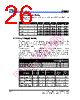
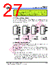
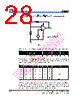
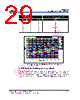
26 / 60 page  EM62100 65 COM/132 SEG STN LCD Driver 20 • ••• Product Specification (V1.1) 09.13.2005 (This specification is subject to change without further notice) 6.11.3 Configuration Setting The EM62100 has two-optional configurations, configured by DUTY0 and DUTY1, as shown in Table 9. Table 9 Duty ratio Duty1 Duty0 LCD bias V1 V2 V3 V4 1/5 (4/5)V0 (3/5)V0 (2/5)V0 (1/5)V0 1/33 0 0 1/6 (5/6)V0 (4/6)V0 (2/6)V0 (1/6)V0 1/6 (5/6)V0 (4/6)V0 (2/6)V0 (1/6)V0 1/49 0 1 1/8 (7/8)V0 (6/8)V0 (2/8)V0 (1/8)V0 1/6 (5/6)V0 (4/6)V0 (2/6)V0 (1/6)V0 1/55 1 0 1/8 (7/8)V0 (6/8)V0 (2/8)V0 (1/8)V0 1/7 (6/7)V0 (5/7)V0 (2/7)V0 (1/7)V0 1/65 1 1 1/9 (8/9)V0 (7/9)V0 (2/9)V0 (1/9)V0 6.12 Power Supply Module The power supply circuits have low power consumption and generate the voltage levels necessary to drive the LCD. There are Booster (step-up voltage) circuits, Voltage regulator circuits, and voltage follower circuits. They are valid only when operating in master mode. The power supply circuit can turn the Booster circuits, the voltage regulator circuits and the voltage follower circuit ON or OFF independently through the Power Control Set command. Consequently, it is possible to make both external and internal power supplies function in parallel. Table 10 shows the Power Control Set Command 3-bit data control function. Table 11 shows the reference combinations. Table 10 Status Item H L D2 Voltage Booster (V/B) circuit control bit ON OFF D1 Voltage Regulator (V/R) circuit control bit ON OFF D0 Voltage Follower (V/F) circuit control bit ON OFF Table 11. Recommended Power Supply Combinations Use Step-up V/B V/R V/F V/B Circuit V/R Circuit V/F Circuit External Voltage Input Step-up Voltage System Terminal Only the internal power supply is used 1 1 1 ON ON ON VEE Used Only the V/R circuit and V/F circuits are used 0 1 1 OFF ON ON VOUT, VEE Open Only the V/F circuit is used 0 0 1 OFF OFF ON V0, VEE Open Only the external power supply is used 0 0 0 OFF OFF OFF V0 to V4 Open |
|
Link URL |
| Does ALLDATASHEET help your business so far? [ DONATE ] |
About Alldatasheet | Advertisement | Contact us | Privacy Policy | Link to Datasheet | Link Exchange | Manufacturer List All Rights Reserved©Alldatasheet.com |
| Russian : Alldatasheetru.com | Korean : Alldatasheet.co.kr | Spanish : Alldatasheet.es | French : Alldatasheet.fr | Italian : Alldatasheetit.com Portuguese : Alldatasheetpt.com | Polish : Alldatasheet.pl | Vietnamese : Alldatasheet.vn Indian : Alldatasheet.in | Mexican : Alldatasheet.com.mx | British : Alldatasheet.co.uk | New Zealand : Alldatasheet.co.nz |
|
Family Site : ic2ic.com |
icmetro.com |
 English ▼
 English
 Chinese
 German
 Japanese
 Russian
 Korean
 Spanish
 French
 Italian
 Portuguese
 Polish
 Vietnamese
 Indian
 Mexican
 British
 New Zealand