|
Electronic Components Datasheet Search |
|
|
Electronic Components Datasheet Search |
|
L9965P Datasheet(PDF) 53 Page - STMicroelectronics |
|
|
|||||||||||||||||||||||||||||
L9965P Datasheet(HTML) 53 Page - STMicroelectronics |
|
|
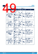
53 / 104 page  Figure 27. ERBST management during ER cap diag ERBST BOOST CTRL D E D E D tER_WKUP_FLT 0.9*VERBST_XXX tDISCHARGE VERBST_XXX VER_WKUP_THX tCHARGE 2V tCHARGE tER_WKUP_FLT tDISCHARGE BOOST CTRL D E D VSUPPLY ΔVER ER cap diag D E D tER_WKUP_FLT tDISCHARGE tCHARGE tCHARGE tER_WKUP_FLT tDISCHARGE E D E E D D ΔVDISCHARGE ΔVER ΔVER E E D The IC performs the sequence of measurements automatically and saves the calculations in the CAP_VALUE[13:0] and ESR_VALUE[12:0] bit fields. A timeout tER_CAP_DIAG_TO for diagnostic duration is present. If it is exceeded, the process is halted and the ERCAP_DIAG_END_TO flag is set in the ERCAP register. If the diagnostic ends within the timeout, the device saves the CAP_VALUE in ERCAP_DIAG_CAP_READ_0 and ERCAP_DIAG_CAP_READ_1 registers, and the ESR_VALUE in ERCAP_DIAG_ESR_READ_0 and ERCAP_DIAG_ESR_READ_1 registers. At this point the IC automatically compares CAP_VALUE and ESR_VALUE with the thresholds previously saved in NVM, respectively ERCAP_C_THR and ERCAP_ESR_THR. The FAULTN line is asserted: • If CAP_VALUE[13:0] < (“00” & ERCAP_C_THR[7:0] & “0000”), and ERCAP_LOW_C flag is set in the ERCAP register. • If ESR_VALUE[12:0] > (ERCAP_ESR_THR[6:0] & “0000”), and ERCAP_HIGH_ESR flag is set in the ERCAP register. Note: A high threshold is defined for capacitance value and a low threshold for ESR since, due to aging and thermal stress, an electrolytic capacitor over the years shows a decrease of the capacitance value and an increase of the ESR. Knowing RERDCHSW, the MCU can check C and ESR calculation values as follows: C=CAP_VALUE13:0 ×LSBC× 1RERDCHSW (6) ESR=ESR_VALUE12:0 ×LSBESR×RERDCHSW (7) Once started, the ER capacitor diagnostic process can only be interrupted by a deployment request. Once a request is over, to proceed with a new one the ER_CAP bit must be left at 1 and the DIAG_START bit in the DIAG_CMD register must be set back to 1 (it returns automatically to 0). The ER capacitor diagnostic step duration is dependent on the capacitor value, as specified by tER_CAP_DIAG1 and tER_CAP_DIAG2. The possible results of ER capacitor diagnostics are reported in the Table 29. L9965P Functional description DS14702 - Rev 4 page 53/104 |
|
Link URL |
| Does ALLDATASHEET help your business so far? [ DONATE ] |
About Alldatasheet | Advertisement | Contact us | Privacy Policy | Link to Datasheet | Link Exchange | Manufacturer List All Rights Reserved©Alldatasheet.com |
| Russian : Alldatasheetru.com | Korean : Alldatasheet.co.kr | Spanish : Alldatasheet.es | French : Alldatasheet.fr | Italian : Alldatasheetit.com Portuguese : Alldatasheetpt.com | Polish : Alldatasheet.pl | Vietnamese : Alldatasheet.vn Indian : Alldatasheet.in | Mexican : Alldatasheet.com.mx | British : Alldatasheet.co.uk | New Zealand : Alldatasheet.co.nz |
|
Family Site : ic2ic.com |
icmetro.com |
 English ▼
 English
 Chinese
 German
 Japanese
 Russian
 Korean
 Spanish
 French
 Italian
 Portuguese
 Polish
 Vietnamese
 Indian
 Mexican
 British
 New Zealand