|
Electronic Components Datasheet Search |
|
|
Electronic Components Datasheet Search |
|
ISL73006SLHDEMO2Z Datasheet(PDF) 21 Page - Renesas Technology Corp |
|
|
|||||||||||||||||||||||||||||
ISL73006SLHDEMO2Z Datasheet(HTML) 21 Page - Renesas Technology Corp |
|
|
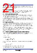
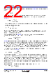
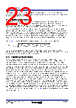
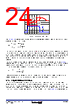
21 / 31 page  R34DS0034EU0101 Rev.1.01 Page 21 Mar 13, 2024 ISL73006SLH Datasheet reach the NOCL, the ISL73006SLH initiates soft-start when VOUT is pulled below the regulation set point. The device is disabled and enters the low current shutdown state when EN is < 0.3V. When a transition to a shutdown state occurs, the LX output is forced to a hi-Z state. 5.10 Thermal Protection The device has integrated thermal protection. When the internal temperature reaches ~ +158°C, the regulator stops switching. After the internal temperature falls below ~ +130°C, the device resumes operation through soft-start. For continuous operation, do not exceed the +150°C junction temperature rating. 5.11 PWM Control and Compensation The ISL73006SLH employs constant frequency peak current-mode pulse-width modulation (PWM) control for faster transient response and pulse-by-pulse current limiting. The current loop consists of the current-sensing circuit, slope compensation ramp, and PWM comparator. Any regulator design starting point is knowing the operating conditions and design goals. These would include the input and output voltages, the switching frequency, the maximum transient current step, and the maximum transient output voltage tolerance. The following compensation equations guide completing an external slope and loop control compensation design. 5.12 Slope Compensation The ISL73006SLH offers user-adjustable slope compensation using a resistor (RSLOPE) from the SLOPE pin to ground to optimize the device performance and stability across the entire PWM duty-cycle range. Slope compensation is a technique in which the current feedback signal is modified by adding slope, that is, a linearly increasing voltage over time. You can set the external slope compensation ramp with a resistor from the slope pin to ground. For applications with a maximum duty cycle of less than 50%, slope compensation can improve noise immunity, particularly at lighter loads. For applications with a greater than 50% duty cycle, you need slope compensation to prevent instability, seen as a sub-harmonic oscillation of the switching LX node. The minimum slope compensation required is -VOUT/2 × output inductor (LOUT). 5.13 External Configuration Application Implementation Equations This section guides the design for the slope and loop compensations along with the loop bandwidth and limiting the output current transient voltage response. Use Equation 2 to set the inductor downslope. The compensation slope is: Due to inductor tolerances and increased noise immunity, Renesas recommends using SL= SCOMP (deadbeat control) so: Due to headroom issues, RSLOPE value must be within 25kΩ ≤ RSLOPE ≤ 100kΩ. Internal slope compensation is set to maximum slope compensation of 0.324. (EQ. 2) (EQ. 3) (EQ. 4) SL VOUT L ---------------- = SCOMP A s ------ 162 RSLOPE k 500 ------------------------------------- = RSLOPE k 62 VOUT V L H ------------------------- = |
|
Link URL |
| Does ALLDATASHEET help your business so far? [ DONATE ] |
About Alldatasheet | Advertisement | Contact us | Privacy Policy | Link to Datasheet | Link Exchange | Manufacturer List All Rights Reserved©Alldatasheet.com |
| Russian : Alldatasheetru.com | Korean : Alldatasheet.co.kr | Spanish : Alldatasheet.es | French : Alldatasheet.fr | Italian : Alldatasheetit.com Portuguese : Alldatasheetpt.com | Polish : Alldatasheet.pl | Vietnamese : Alldatasheet.vn Indian : Alldatasheet.in | Mexican : Alldatasheet.com.mx | British : Alldatasheet.co.uk | New Zealand : Alldatasheet.co.nz |
|
Family Site : ic2ic.com |
icmetro.com |
 English ▼
 English
 Chinese
 German
 Japanese
 Russian
 Korean
 Spanish
 French
 Italian
 Portuguese
 Polish
 Vietnamese
 Indian
 Mexican
 British
 New Zealand