|
Electronic Components Datasheet Search |
|
|
Electronic Components Datasheet Search |
|
ISL73006SLHDEMO2Z Datasheet(PDF) 22 Page - Renesas Technology Corp |
|
|
|||||||||||||||||||||||||||||
ISL73006SLHDEMO2Z Datasheet(HTML) 22 Page - Renesas Technology Corp |
|
|
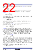
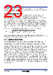
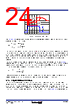
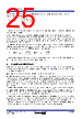
22 / 31 page  R34DS0034EU0101 Rev.1.01 Page 22 Mar 13, 2024 ISL73006SLH Datasheet RCOMP value is set by transient response requirement. We need to know Equation 6 and the transient step value ΔIOUT. We also need error amp transconductance (gm = 0.923mA/V) and modulator transconductance (GM = 4A/V, which means 250mV voltage step at COMP node causes 1A output current step). Calculate RCOMP using Equation 6. Internal compensation is set in such a way as to ensure ±2% VOUT transient response for ±0.5A load current step. CCOMP defines compensator zero frequency: Set fz to ft/10 to maximize phase margin. However, this slows down transient response recovery time. You can reduce this time by increasing fz (at the expense of the phase margin). In general, zero frequency should not exceed ft/3 (12.7deg loss of phase margin). When RCOMP is determined, use Equation 8 to calculate the output capacitance, where gm = 0.923mS, GM = 4A/V, VREF = 0.6V, and unity gain frequency ft is typically fSW/10. Equation 8 does not guarantee that transient response is met in all cases. The main reason is the nonlinear nature of the switching regulator. To derive equations, approximate the modulator with a simple (and linear) GM stage, which means any fast dV/dt at the input of GM produces equally fast dI/dt at the output. Because the output inductor (L) limits dI/dt (dI/dt = V/L), in some cases (typically extremely low D or extremely large D), the current slew rate dI/dt = V/L might get limited by V/L in which case transient response is going to be larger than expected. In those cases, you must reduce L to increase dI/dt or increase COUT to slow down dV/dt at the GM input. In the case of internal compensation (set for ±2% VOUT transient response with ±0.5A load current step), calculate COUT_MIN using Equation 9: Equations are derived for ideal COUT. Treat MLCCs as ideal capacitors because of small parasitic components (ESR and ESL). In cases where you cannot use them, carefully consider the ESR value. In the case of extremely fast transients (1A/ns for microprocessors), voltage drop (ESR x dI) appears extremely quickly, and the regulation loop cannot react that fast. In those cases, you need to increase COUT. Transient response effectively has two components (ESR and COUT). The solution is to reduce COUT transient by the ESR x dI product value. For example, if 2% transient is required and ESR x dI causes 0.5% transient response, 1.5% transient should be used to determine RCOMP. Regarding loop stability, ESR zero must be canceled by a pole created with CPOLE such that: (EQ. 5) (EQ. 6) (EQ. 7) (EQ. 8) (EQ. 9) (EQ. 10) k V OUT VOUT -------------------- = RCOMP I OUT kVREFgmEAGM --------------------------------------------- = fz 1 2 R COMPCCOMP --------------------------------------------------- = COUT_MIN VREFgmGMRCOMP 2 ftVOUT -------------------------------------------------------- = COUT_MIN F 40000 2 f t kHz V OUT V ---------------------------------------------------- = ESR COUT RCOMPCPOLE = |
|
Link URL |
| Does ALLDATASHEET help your business so far? [ DONATE ] |
About Alldatasheet | Advertisement | Contact us | Privacy Policy | Link to Datasheet | Link Exchange | Manufacturer List All Rights Reserved©Alldatasheet.com |
| Russian : Alldatasheetru.com | Korean : Alldatasheet.co.kr | Spanish : Alldatasheet.es | French : Alldatasheet.fr | Italian : Alldatasheetit.com Portuguese : Alldatasheetpt.com | Polish : Alldatasheet.pl | Vietnamese : Alldatasheet.vn Indian : Alldatasheet.in | Mexican : Alldatasheet.com.mx | British : Alldatasheet.co.uk | New Zealand : Alldatasheet.co.nz |
|
Family Site : ic2ic.com |
icmetro.com |
 English ▼
 English
 Chinese
 German
 Japanese
 Russian
 Korean
 Spanish
 French
 Italian
 Portuguese
 Polish
 Vietnamese
 Indian
 Mexican
 British
 New Zealand