|
Electronic Components Datasheet Search |
|
|
Electronic Components Datasheet Search |
|
ATtiny48 Datasheet(PDF) 67 Page - ATMEL Corporation |
|
|
|||||||||||||||||||||||||||||
ATtiny48 Datasheet(HTML) 67 Page - ATMEL Corporation |
|
|
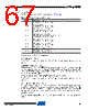
67 / 266 page  67 8008C–AVR–03/09 ATtiny48/88 10.3.3 Alternate Functions of Port C The Port C pins with alternate functions are shown in Table 10-8. The alternate pin configuration is as follows: • PCINT15 – Port C, Bit 7 PCINT15: Pin Change Interrupt source 15. The PC7 pin can serve as an external interrupt source. • RESET/PCINT14 – Port C, Bit 6 RESET, Reset pin: When the RSTDISBL Fuse is programmed, this pin functions as a normal I/O pin, and the part will have to rely on Power-on Reset and Brown-out Reset as its reset sources. When the RSTDISBL Fuse is unprogrammed, the reset circuitry is connected to the pin, and the pin can not be used as an I/O pin. If PC6 is used as a reset pin, DDC6, PORTC6 and PINC6 will all read 0. PCINT14: Pin Change Interrupt source 14. The PC6 pin can serve as an external interrupt source. • SCL/ADC5/PCINT13 – Port C, Bit 5 SCL, 2-wire Serial Interface Clock: When the TWEN bit in TWCR is set (one) to enable the 2- wire Serial Interface, pin PC5 is disconnected from the port and becomes the Serial Clock I/O pin for the 2-wire Serial Interface. In this mode, there is a spike filter on the pin to suppress spikes shorter than 50 ns on the input signal, and the pin is driven by an open drain driver with slew-rate limitation. PC5 can also be used as ADC input Channel 5. Note that ADC input channel 5 uses digital power. Table 10-8. Port C Pins Alternate Functions Port Pin Alternate Function PC7 PCINT15 (Pin Change Interrupt 15) PC6 RESET (Reset pin) PCINT14 (Pin Change Interrupt 14) PC5 ADC5 (ADC Input Channel 5) SCL (2-wire Serial Bus Clock Line) PCINT13 (Pin Change Interrupt 13) PC4 ADC4 (ADC Input Channel 4) SDA (2-wire Serial Bus Data Input/Output Line) PCINT12 (Pin Change Interrupt 12) PC3 ADC3 (ADC Input Channel 3) PCINT11 (Pin Change Interrupt 11) PC2 ADC2 (ADC Input Channel 2) PCINT10 (Pin Change Interrupt 10) PC1 ADC1 (ADC Input Channel 1) PCINT9 (Pin Change Interrupt 9) PC0 ADC0 (ADC Input Channel 0) PCINT8 (Pin Change Interrupt 8) |
|
Link URL |
| Does ALLDATASHEET help your business so far? [ DONATE ] |
About Alldatasheet | Advertisement | Contact us | Privacy Policy | Link to Datasheet | Link Exchange | Manufacturer List All Rights Reserved©Alldatasheet.com |
| Russian : Alldatasheetru.com | Korean : Alldatasheet.co.kr | Spanish : Alldatasheet.es | French : Alldatasheet.fr | Italian : Alldatasheetit.com Portuguese : Alldatasheetpt.com | Polish : Alldatasheet.pl | Vietnamese : Alldatasheet.vn Indian : Alldatasheet.in | Mexican : Alldatasheet.com.mx | British : Alldatasheet.co.uk | New Zealand : Alldatasheet.co.nz |
|
Family Site : ic2ic.com |
icmetro.com |
 English ▼
 English
 Chinese
 German
 Japanese
 Russian
 Korean
 Spanish
 French
 Italian
 Portuguese
 Polish
 Vietnamese
 Indian
 Mexican
 British
 New Zealand